
Getting a Civil 3D TIN Ready for Model Review
Civil 3D can make some remarkably sophisticated surface displays.
Elevation analysis. Slope analysis. Contours. Watersheds. Directions. Heat maps in enough colours to make a meteorologist jealous.
That's useful when you're doing civil design.
It's considerably less useful when you're sitting in a multidisciplinary model review and somebody from piping asks:
“Okay... but what's gravel?”
This is the problem that eventually became Ross ET-002.
For many of us, the finished Civil 3D model doesn't stay in Civil 3D.
We need to get the TIN into Navisworks or another coordination environment so piping, structural, mechanical, project management and the client can walk through the project together.
And those other disciplines have an advantage.
Their models already look like things.
A pipe looks like a pipe.
Steel looks like steel.
Equipment looks like equipment.
Civil arrives with a triangulated surface.
Behold. Ground.
We know one portion is gravel, another is common fill, another is a lined pond, another is a road and another is water. We designed it.
Everyone else sees triangles.
Exactly.
That's what we'd like to do too.
Civil 3D gives us plenty of ways to analyse a surface internally. We can colour by elevation, slope, direction and any number of other useful engineering properties.
But that's not necessarily what we need for a project walkthrough.
Piping doesn't particularly care that an area is between 2% and 5% slope.
They may not even believe slope is a real word.
What they need to understand is:
That's the gravel road.
That's the operating pad.
That's common fill.
That's the lined area.
That's the pond.
That's water.
No explanation of Civil 3D surface styles required.
No slope-analysis legend.
No civil designer sitting beside everyone translating the TIN.
Just a model that visually communicates the design.
That's the customer we had in mind when we built Ross.
Because we're that customer too.
Native Materials and Region Preparation
Civil 3D already lets designers assign render materials and manipulate surface triangles. A designer can manually identify bounded regions and apply the required material assignments using the appropriate native workflow. Render-only surface masks are one native way to apply a material within or outside a defined boundary; they are distinct from editing the triangle geometry itself.
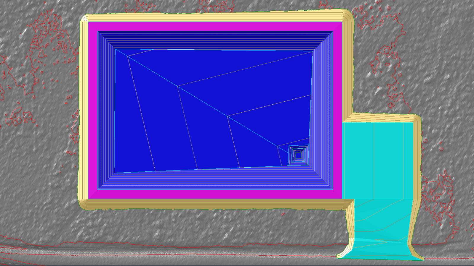
Ross automates the repetitive region-detection and colouring workflow. The designer still chooses the materials or surface treatments and reviews the result. Ross recognizes usable regions in the selected design geometry; it does not decide that an area should be gravel, water or another material on the designer’s behalf.
Autodesk reference: surface masks and render materials
See Ross use the model’s regions to help separate surface triangles visually, with material choices left to the designer.
Watch the Ross Short on YouTube →
The TIN already knows where every triangle is.
And the civil designer generally already has geometry defining the areas that mean something: Feature Lines, grading limits, road edges, pond boundaries, pad limits, corridor features and other design linework.
The frustrating part is connecting those two things.
Traditionally, preparing all of those individual surface regions for model review can become a surprisingly manual process.
So we approached Ross differently.
We didn't want the designer carefully feeding it one perfect boundary at a time.
We wanted to be able to say:
Here's the surface. Here's the design geometry. You figure it out.
Our typical workflow is deliberately simple:
- Finish the civil surface.
- Select the applicable design geometry around it.
- Let Ross determine what actually forms usable boundaries.
- Choose the material or surface treatment you want to apply.
- Identify the region.
- Let Ross determine which TIN triangles belong inside it.
- Preview the result.
- Finish it.
- Export a civil model that the rest of the project team can actually understand.
Step 2 is important.
This is an overall selection.
You don't need to carefully identify and construct every individual closed boundary before Ross can get to work. Select the applicable design geometry and Ross sorts through it to determine what can actually form bounded regions.
You define the design intent.
Ross does the boundary sorting and triangle archaeology.
This is where Ross stopped being an interesting experiment for us and became something we genuinely wanted to use.
An Observed Workflow Example
Preparing a Civil 3D surface for multidisciplinary model review can take hours of repetitive work, particularly when a site contains multiple roads, pads, ponds, lined areas and other material regions.
In our internal workflows, Ross has taken work that previously required hours and reduced it to minutes, cutting the time required by as much as approximately 90% in some cases.
That's not a promise that every model will be 90% faster.
Civil drawings have far too much personality for us to make that claim.
It's what we've observed internally on the kinds of real-world workflows Ross was built to solve.
And our internal users like it.
We do too.
That matters more than it might sound.
Saving time is useful.
Saving time with a tool you actually enjoy using is considerably better.
Ross has become one of those tools where, after preparing a model with it, going back to the old workflow feels remarkably unattractive.
Ross has geometry to process, so model complexity matters.
A relatively simple TIN with clean design geometry will naturally process faster than an enormous, highly detailed surface containing complicated grading and corridor geometry.
That's expected.
It's also worth remembering when preparing a model specifically for coordination.
If the model review doesn't benefit from every last piece of design complexity, don't bring every last piece of design complexity.
The simplest model that accurately communicates the design is usually the better coordination model anyway.
Your computer will also appreciate the gesture.
Feature Lines, Corridors and Model Complexity
Ross isn't limited to simple grading surfaces.
Corridor-based designs can be used as well.
Where corridor geometry is involved, Auto Corridor Feature Lines can be included with the overall geometry selection, giving Ross additional design geometry from which to identify applicable bounded regions.
That means a roadway or other corridor-based design doesn't necessarily require you to manually recreate all of its material limits simply for model presentation.
Include the appropriate Auto Feature Lines with the other applicable design geometry and let Ross sort out what can form useful regions.
Naturally, more geometry means more processing.
A simple pad surface is going to be quicker than a complicated corridor containing a small civilization's worth of triangles.
Ross doesn't mind. He just needs a little longer to think about it.
One of the more useful Ross workflows we've discovered has nothing to do with proposed grading at all.
Suppose you're starting with an existing LiDAR surface.
Geometrically, it may be excellent.
Visually, it's still a TIN.
You may also have as-built Feature Lines, survey linework, road edges, ditch lines or other existing site information.
Or you may have something considerably less elegant.
An old sketch.
An aerial image.
Some recognizable features in the LiDAR.
And twenty minutes of staring at the screen saying:
“I'm pretty sure that's the road edge.”
That's useful too.
If you can reasonably interpret the limits of existing features, you can create or use that geometry, drape it onto the existing-ground surface and include it in the geometry Ross works with.
That can let you visually distinguish features such as:
- existing roads;
- gravel areas;
- disturbed or operating areas;
- pads;
- ditches and drainage features;
- ponds or water;
- other recognizable existing site limits.
You don't necessarily need a beautifully prepared existing-condition CAD model before you can produce something useful for coordination.
Sometimes LiDAR plus survey information and a reasonable interpretation of the site is what you've got.
Work with it.
LiDAR is very good at telling us where the ground is. It is considerably less interested in telling piping what the ground is for.
Ross can help bridge that gap.
That's really the point of Ross.
It isn't about colouring a Civil 3D surface because coloured surfaces look nicer.
It's about communicating civil design information outside Civil 3D.
When the model moves into Navisworks or another multidisciplinary environment, those material and surface regions mean something.
Piping can see the road.
Structural can see the pad.
The client can see the pond.
Operations can distinguish one surface treatment from another.
And nobody needs the civil designer sitting beside them explaining what the purple-to-yellow slope heat map is trying to say.
Progress.
Ross came directly from this multidisciplinary workflow.
Piping could produce a model that looked like piping.
Structural could produce a model that looked like structural.
Civil 3D could produce an extraordinarily accurate triangulated representation of the ground...
...that looked remarkably like an extraordinarily accurate triangulated representation of the ground.
We wanted more.
Not another analytical heat map.
Not another Civil 3D display that only makes sense while you're inside Civil 3D.
We wanted a civil model that could leave our software and communicate the design visually to everybody else in the room.
So we built Ross.
And once it started turning hours of model-preparation work into minutes, we became rather attached to it.
Ross ET-002 is available now for Civil 3D 2024–2027.
Try Ross free for three days in your own model-review workflow. No credit card or automatic charge. The corporate offer is CA$299/year per concurrent seat.
Ross does not replace Civil 3D’s surface or material tools. It accelerates the repetitive work between them—recognizing the regions already defined by the model and helping the designer apply deliberate visual separation much faster.
For the complete model-preparation workflow, watch the full Ross demonstration.
Ross ET-002 — Available Now