
Field Notes / Ross
Add Culverts and Riprap to 3D Model Reviews
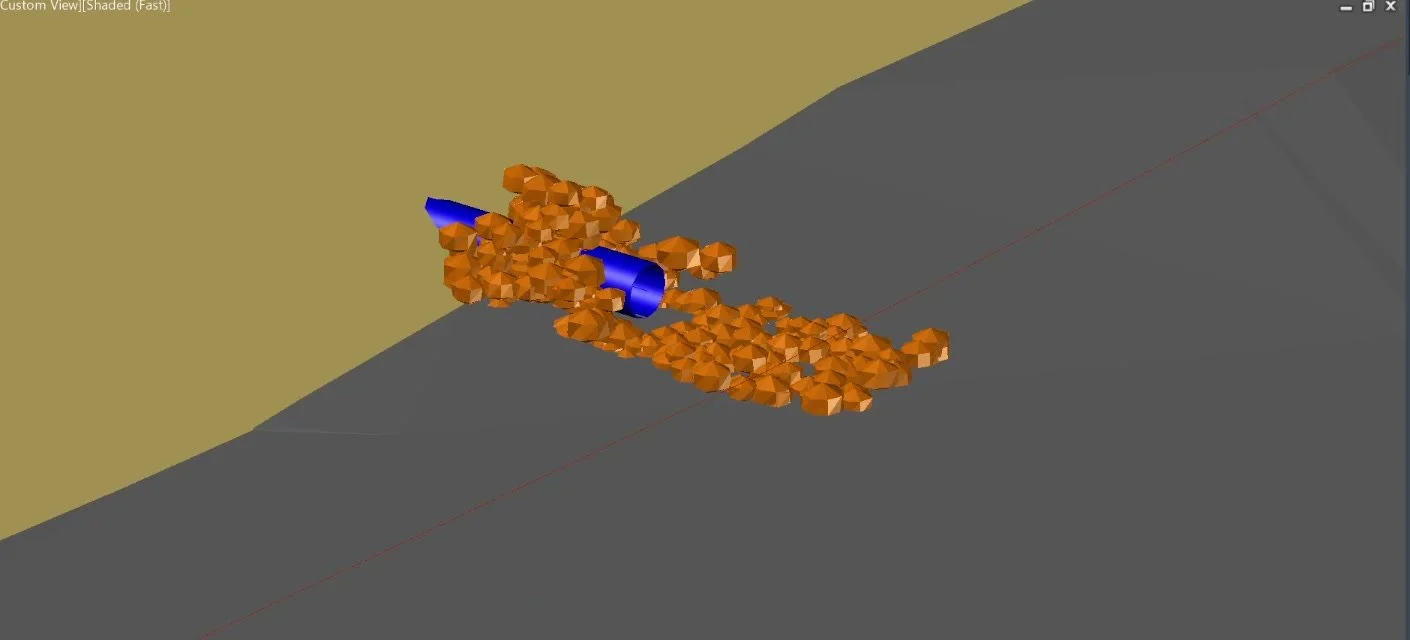
The culvert is on the plan. The outlet protection has a hatch and a note. The grading is in the surface.
Then the project goes into a walkthrough and somebody asks where the drainage goes.
Nothing is necessarily missing from the design. What is missing is the visual connection between the crossing, the ground and the protection around it.
Three-dimensional culvert and riprap modelling can make the relationship between a crossing, the ground and its protection much easier to understand. The challenge is producing useful review geometry without spending the afternoon building a pipe and manually arranging individual rock solids or meshes.
Ross model-review tools include culvert and riprap workflows for adding that context. They help represent the intended work in 3D so the review can focus on the site.
Bring the design information to the model
Start with the design information that establishes the crossing: location, orientation, relevant levels, size and length. For protection areas, establish the intended extent and relationship to the ground.
Those decisions come from the design. The modelling step should communicate them consistently, not invent them because a particular arrangement looks better on screen.
Keep the purpose of the representation clear as well. A review of an outlet beside an access road may need the crossing and apron to read from an oblique view. It may not need detailed pipe joints or individually meaningful rock geometry.
Choose the detail that helps answer the review question. Extra geometry has to earn its place.
From the drafting plan to the 3D review
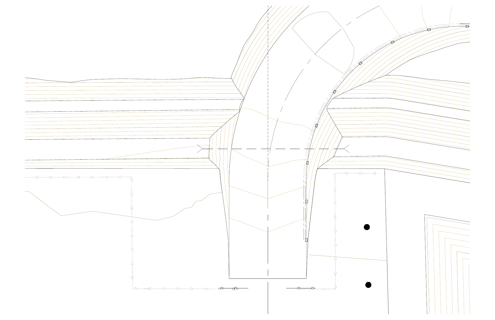
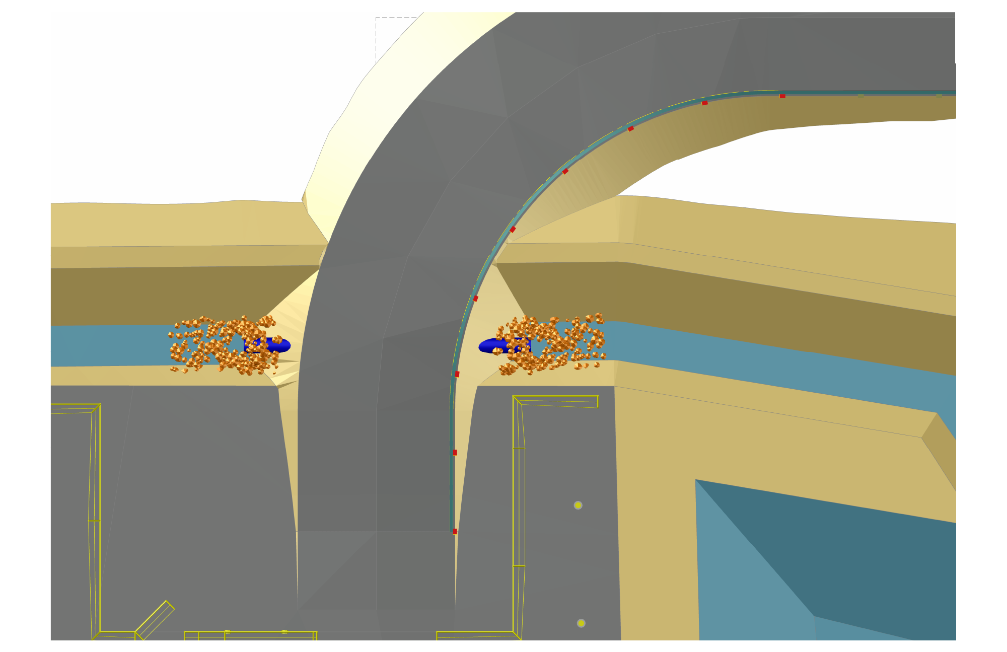
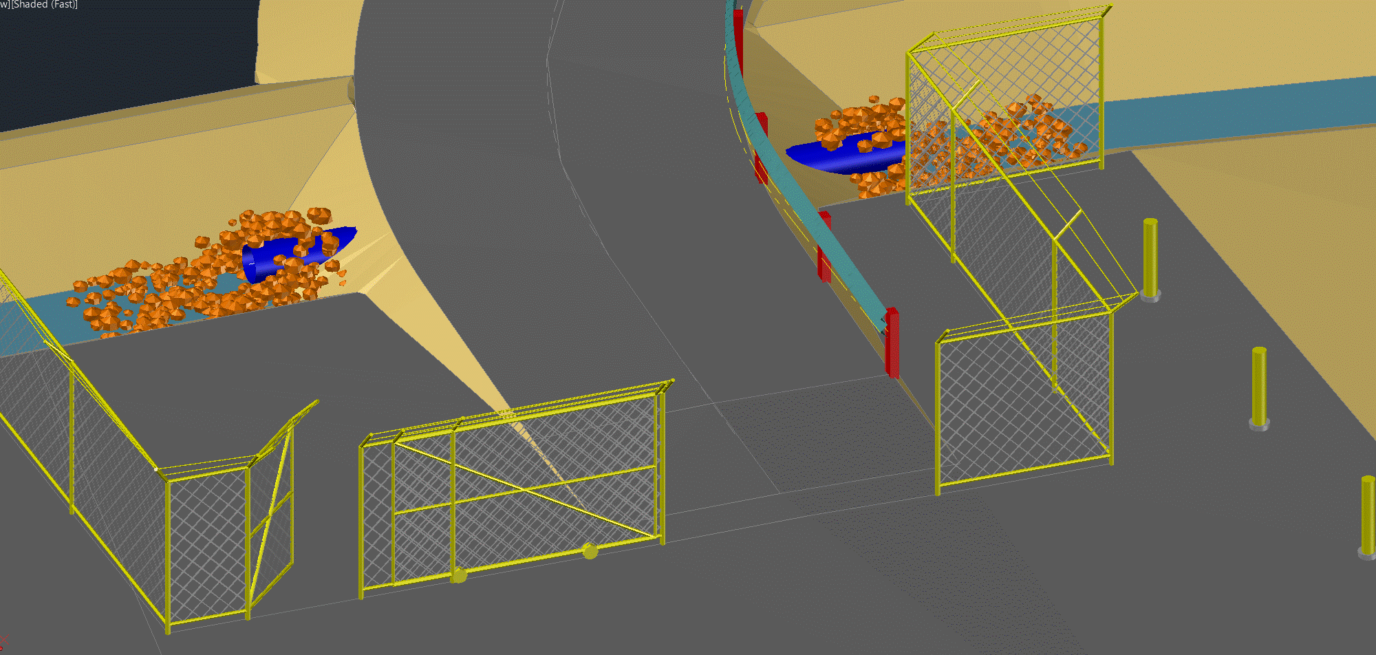
These views show the road entrance and crossing in linework, shaded plan and an oblique model view. They illustrate how the fence, gates, culvert, riprap, guardrail and bollards give the design visible context.
Why the manual version often gets left out
A simple culvert representation can be built manually. Position it, orient it, adjust it to the crossing and check how it meets the ground. That is reasonable for an isolated example.
The work grows when the crossing moves, the length changes or several locations need the same treatment. Every revision asks the modeller to revisit geometry whose main purpose is to explain another part of the design.
Riprap is an even clearer example. A hatch communicates an area in plan, but it does little for an eye-level walkthrough. Individual rock objects can suggest the intended treatment, but placing and maintaining them one at a time is a poor use of design time.
That is why the protection may be well documented and still almost invisible in the review model.
Show the crossing and its outlet together
Ross builds the culvert from an open, simple AutoCAD 3D polyline used as the centreline. Set Culvert Diameter (inside) and Wall Thickness; Ross creates the culvert solid and preserves the centreline. Later, select the Ross culvert, choose Rebuild and revise those dimensions. Ross rebuilds the solid from the saved centreline without making you recreate the crossing manually.
Create a culvert and add riprap
Watch the crossing workflow, including culvert placement, riprap and a scale-and-rebuild sequence.
Ross uses the selected native 3D polyline to create standard AutoCAD solid geometry for the culvert. The generated object and its saved Ross data support later dimension changes and rebuilds inside the supported Ross environment.
The important inspection is the relationship between objects. Does the culvert read as passing through the intended crossing? Is the outlet visible? Does the protection appear where the design calls for it, with a sensible relationship to the surrounding ground?
A viewer should be able to follow that story without switching back to the plan every few seconds. The geometry makes the arrangement easier to discuss alongside the design information.
Culvert protection and slope riprap answer different questions
Culvert riprap begins with the culvert. Select a Ross culvert solid and choose the end to treat. Ross uses the culvert’s axis and dimensions to position the protection. Apron length, treatment width and rock settings control the generated protection around that end.
Place protection around the culvert
This earlier demonstration shows culvert and riprap placement followed by scale and rebuild; Ross is available now.
Area or slope riprap begins with a closed native AutoCAD polyline or 3D polyline boundary. Ross generates standard drawing geometry within that footprint using the selected rock and mat settings. Use a closed, straight-segment polyline or simple 3D polyline; add any no-riprap exclusion polygons, and define the supporting plane. Choose Level for a flat treatment or ThreePoint to establish a sloping plane from three picked points. This sets the mat’s position and slope; it is not automatic draping over an arbitrary terrain surface.
The boundary controls the extent; the support plane controls the elevation and slope. Together they make a protected area readable in the review model.
Build riprap on a slope
Watch Ross preview and build rock coverage for a sloping protection area.
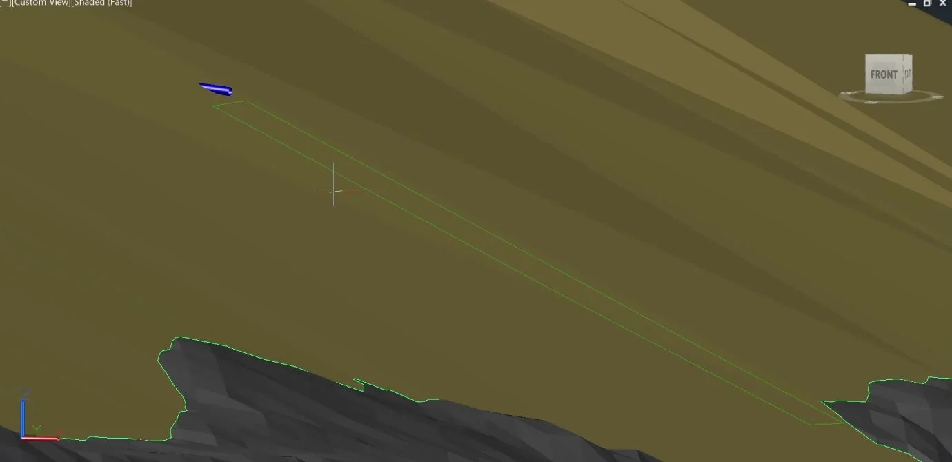
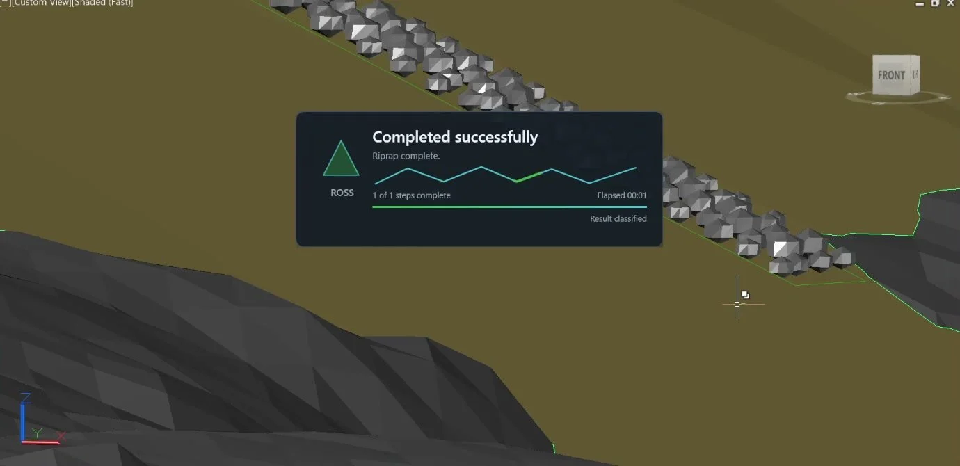
Watch the slope-riprap workflow
Select the protection footprint, establish the support plane, then preview and build the riprap.
A revision worth testing before the review
Consider a crossing where a grading revision changes the visible outlet position and the intended protection extent. This is an illustrative example, not a project case study.
First, resolve the revised design information. For a culvert size change, select the generated culvert, choose Rebuild and use Dimensions to enter the revised inside diameter and wall thickness. For culvert riprap, select one of its generated rocks to rebuild the protection with the revised apron, treatment and rock settings.
For an area mat, revise the boundary or supporting-plane inputs and rebuild the mat. These are explicit rebuild workflows: after changing the design, update the related geometry rather than assuming every object changes automatically.
Inspect the revised crossing in plan and oblique views. Check that the old representation has not been left beside the new one, that the culvert still relates properly to the ground and that the riprap footprint reflects the intended revision.
Before export or federation, check the drawing result. Then check the actual review file, including the appearance and visibility of the outlet and protection. A hidden apron contributes very little to a walkthrough.
Keep the surrounding terrain readable
Culverts and riprap are easier to understand when the surface around them provides context. Roads, pads, ponds and other material areas help orient the reviewer.
Our Field Note on Civil 3D TIN surface colouring for model review covers that related problem. Use the surface and site objects together to explain the arrangement, while keeping the underlying engineering information authoritative.
Common questions
Does Ross perform hydraulic culvert design?
Ross creates practical, revisable 3D geometry for model reviews. Hydraulic sizing, scour assessment and protection design remain with the underlying engineering design.
Can the representation be resized and rebuilt?
Yes. The culvert Rebuild workflow reloads the saved centreline and dimensions. Change the inside diameter and wall thickness, accept the settings, and Ross replaces the culvert solid.
What stays editable?
Culvert dimensions can be revised through Rebuild. Culvert riprap has apron length, treatment width and rock settings. Area riprap retains its boundary, exclusions, support plane and mat settings for its rebuild workflow. Try a size change and a protection-area revision during your evaluation.
Can I use the rocks for certified quantities or grading?
The approximate rock representation is for visual context. It does not certify rock grading, placed volume, protection thickness or construction compliance. Use the project’s design and quantity methods for those purposes.
Evaluate one crossing and one revision
A useful trial can be small: one crossing, one protection area and one change. Check whether the model becomes easier to understand and whether maintaining that context fits the way you work.
For the broader reasoning behind these tools, read The Model Review Gap.
The current Ross release supports Autodesk Civil 3D 2024–2027.
Request a free three-day Ross trial. No credit card or automatic charge. Trial requests are manually reviewed.